1) I am trying to formulate how I might implement a demand response (DR) system where a some service demand from one timeslice can be shifted to an adjacent timeslice. I have a model with 8 timeslices in a representative day and was planning to implement as a NST (or STGTSS) technology.
The main idea is that when implemented, the DR system can do load shifting from one timeslice to another, but with a constraint that the shift can only occur between adjacent timeslices. That is, if demand reduction (discharging of storage) occurs in timeslice 5 (of 8), the corresponding demand increase (charging of storage) is constrained to occur in timeslice 4 or 6. This can, for example, represent thermal systems where you can pre-cool a building or freezers so that demand is lessened during the peak hour and shifted before and after the peak hour.
Is this possible? And if so, how might I be able to implement such a constraint?
2) I can see how I might be able to implement an NST where I set the allowable charging timeslices, but there is no way to set the allowable discharging timeslices, correct? It looks like any non-charging timeslice is a discharging timeslice.
Just
some small quick comments (not able to digest all the details):
1) I
would say that yes, you can implement the constraint(s) if it they can be
formulated by linear equations. But to say how, would require first seeing the
equations and the variables involved;
2) Yes,
you are right that for a DAYNITE level NST, any charging ("night")
timeslices are disallowed from being also discharging timelices, and
discharging can only occur in any of the non-charging timeslices (I believe
that NST is basically a relic from MARKAL); in my opinion this characteristic
also makes a DAYNITE level NST often useless for demand technologies, because
some demand usually occurs also during the "night" timeslices, but simply
cannot be met with an NST;
3) I
think it is easy to bound the discharging (or charging) flows to zero in any individual
timeslices, and thereby set the allowable timeslices either for NST or regular
timeslice storage.
My thought is to create a DR process that is a storage device, for example, for space cooling (SC) demand. The process is called SCDR. The input/output are SC_in and SC_out. The goal is to have a constraint such that SC_in,ts - k1*SC_out,ts-1 - k2*SC_out,ts+1 = 0. That is, the amount of cooling that can be taken out of storage in two distinct time slices (ts -1 and ts +1) is equal to the amount of storage added to a given timeslice (ts) and scaled by specific factors (k1 and k2 can be thought of as the inverse of efficiency parameters).
This is a linear constraint, but I’m not sure how to represent these parameters in a VEDA sheet. Any help with this or examples of similar constraints would be appreciated.
So I could set up my constraint as described above, or your 3rd point is a good one as well. I could just set up storage more conventionally and just bound the outputs to zero for several time slices. Again, I’m not entirely sure how to do this in VEDA. Any examples you can provide to create a constraint for setting the output of a storage process to zero for a given timeslice would be greatly appreciated.
Bound
attributes are among the most frequently used parameters in TIMES models. I am
surprised if you have never used ACT_BND, NCAP_BND, CAP_BND, FLO_BND… and STGIN_BND/STGOUT_BND.
The last two parameters are for the storage flows.
(See example in the Appendix if not familiar with TIMES bound parameters)
Your
formulation for the constraint looks very simple indeed, although I am not sure
I am able to see the ”whole picture”. As far as I can see, it involves a single new
technology with just three active timeslice-specific flows (the three flows referred
to in your equation), for a DAYNITE level demand SC. I can see two options for
accomplishing the described goal:
Use a
normal process (without any usual transformation), define the constraint
for the three timeslice-specific flows according to your formulation, and
bound all the remaining flows to zero
Use a
storage process, and bound all the remaining timeslice-specific flows to
zero
It
would be possible to define your constraint also for a storage process, but
that would imply redundant transformation equations that could easily become
inconsistent, and so would not really recommend that option.
The
second option should work fine when k1=k2 (=1/STG_EFF), and involves just bounding
all the flows not included in the constraint to zero. The first option can be
easily implemented by a user constraint with any (k1,k2), by defining the UC_FLO
coefficients for the flow variables, exactly as in your equation. And bounding
the remaining flows to zero is straightforward.
(See example specification
in the Appendix if not familiar with TIMES user constraints)
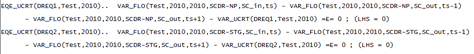
The
resulting user constraint equations (for two example processes, more details in
the Appendix) are shown here, assuming for simplicity that k1=k2=1 in this
example:
Comparing
to your formulation SC_in,ts –
k1*SC_out,ts-1 – k2*SC_out,ts+1 = 0, and recalling the VAR_UCRT is the
slack variable defined to be zero, one can immediately see that both equations
are fully equivalent with your
formulation. But as mentioned above, I would suggest not using the second
equation (for the storage process SCDR_STG).
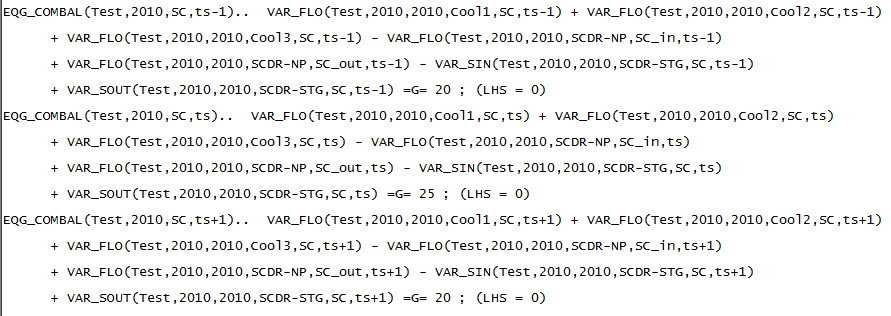
To
verify that the commodity balance for SC is correct, see it below for ts,
ts–1,
and ts+1:
As
you can see, the SC_in and SC_out flow variables for the process SCDR_NP are
correctly included in the SC balance, just like the VAR_SIN/VAR_SOUT storage
variables are for the process SCDR_STG.
I didn't thank you yet for your very detailed
reply. I have been busy and have just gotten around to trying to
implement this structure in my model, but I'm still stuck on a few points which
I will try to highlight, in hopes that you can clarify. I appreciate your
indulging my somewhat simple questions, as I still have lots to learn and
appreciate your help.
I really appreciate the detailed description
including images of the VEDA tables but apparently I need a little bit more
guidance.
Antti-L Wrote:
Bound
attributes are among the most frequently used parameters in TIMES models. I am
surprised if you have never used ACT_BND, NCAP_BND, CAP_BND, FLO_BND… and STGIN_BND/STGOUT_BND.
The last two parameters are for the storage flows.
I have used bound attributes but never in relation to timeslices, just on an annual basis so I did not understand how to set that up.
Antti-L Wrote:
(See example in the Appendix if not familiar with TIMES bound parameters)
Thank you for the detailed Appendix with examples, again it is very helpful.
As I started to go through my model and the specific example that I was trying to implement, I realized that there is a slight wrinkle and a slight modification of the original specifications of the problem. Our service demands are have a timeslice profile (specified by COM_FR table) but the end-use (demand) processes are specified as annual, such that only the electricity input is daynite. This change was made awhile ago to significantly reduce the model run-time, as we do not need or want the model to try to optimize which timeslices to operate these technologies, but rather want all technologies to operate over the same timeslice profile.
To prevent our having to change all of our end-use processes to Daynite processes, I am proposing an alternative solution which is that the demand response technology will be upstream of the end-use technology and the inputs and outputs are electricity. The output electricity of this demand response technology will be the same as the service demand profile (and be an input to our final demand technologies) and the input electricity will be shifted as we discussed in earlier posts (by one timeslice).
Antti-L Wrote:
Your
formulation for the constraint looks very simple indeed, although I am not sure
I am able to see the ”whole picture”. As far as I can see, it involves a single new
technology with just three active timeslice-specific flows (the three flows referred
to in your equation), for a DAYNITE level demand SC. I can see two options for
accomplishing the described goal:
Use a
normal process (without any usual transformation), define the constraint
for the three timeslice-specific flows according to your formulation, and
bound all the remaining flows to zero
Use a
storage process, and bound all the remaining timeslice-specific flows to
zero
It
would be possible to define your constraint also for a storage process, but
that would imply redundant transformation equations that could easily become
inconsistent, and so would not really recommend that option.
The
second option should work fine when k1=k2 (=1/STG_EFF), and involves just bounding
all the flows not included in the constraint to zero. The first option can be
easily implemented by a user constraint with any (k1,k2), by defining the UC_FLO
coefficients for the flow variables, exactly as in your equation. And bounding
the remaining flows to zero is straightforward.
Per your suggestion, I am trying to implement the normal process.
Antti-L Wrote:
(See example specification
in the Appendix if not familiar with TIMES user constraints)
The
resulting user constraint equations (for two example processes, more details in
the Appendix) are shown here, assuming for simplicity that k1=k2=1 in this
example:
Comparing
to your formulation SC_in,ts –
k1*SC_out,ts-1 – k2*SC_out,ts+1 = 0, and recalling the VAR_UCRT is the
slack variable defined to be zero, one can immediately see that both equations
are fully equivalent with your
formulation. But as mentioned above, I would suggest not using the second
equation (for the storage process SCDR_STG).
To
verify that the commodity balance for SC is correct, see it below for ts,
ts–1,
and ts+1:
As
you can see, the SC_in and SC_out flow variables for the process SCDR_NP are
correctly included in the SC balance, just like the VAR_SIN/VAR_SOUT storage
variables are for the process SCDR_STG.
I'm not entirely sure where to view these equations. I'm assuming this is something that VEDA/TIMES is generating. Can you point me to the file/folder where I can view these equations for my own model? Thanks.
this is a followup to the previous post with additional questions on the PDF appendix you were kind enough to provide.
Antti-L Wrote:
Appendix. Additional material for the SCDR example
Here is an example commodity table, including SC_in and SC_out as dummy commodities:
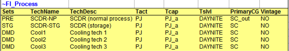
SC_in and SC_out are of LimType N, and will thus not have any commodity balance. Here is an example process table:
As one can see, two new processes SCDR_NP and SCDR_STG are added, in addition to regular demand processes Cool1, Cool2, and Cool3. SCDR_NP is a normal process with PG=SC_out, and SCDR_STG is a storage process with PG=SC.
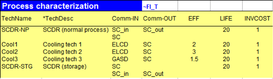
Here is the process characterization table for these example technologies:
As one can see, the two example SCDR processes both have SC and SC_in as inputs, and SC_out as an ouput. For the storage process, SC_in and SC_out are auxiliary flows needed if VAR_SIN and VAR_SOUT variables are to be referred in user constraints. The numerical parameters are arbitrary (and not necessary at all for the SCDR processes).
I'm a little confused by the SCDR-NP process and why it uses both SC_in and SC as inputs. My original intent was that the SCDR technology is downstream of the demand processes (Cool1-3) so the outputs of Cool1-3 would be SC_in. Then SCDR-NP would take SC_in as an input and SC_out (or rather SC) as an output. But as stated in the last post, the specification of the demand processes (Cool1-3) as ANNUAL processes means that I think this will not work, but I am open to ideas.
My alternative idea is instead to put the DR technology upstream of the demand processes such that the electricity output of the DR technology would be the electricity input to Cool1-3 and would match the timeslice profile of the service demand, but that the electricity input to the DR technology would be shifted somewhat based upon the discussion in earlier posts (by one timeslice).
Antti-L Wrote:
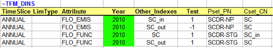
To complete the SCDR process descriptions, the following additional parameters are defined:
The FLO_EMIS parameters take care of the SC balance for SCDR_NP, and the FLO_FUNC parameters define auxiliary flows SC_in and SC_out to be equal to VAR_SIN(SC) and VAR_SOUT(SC) for SCDR_STG.
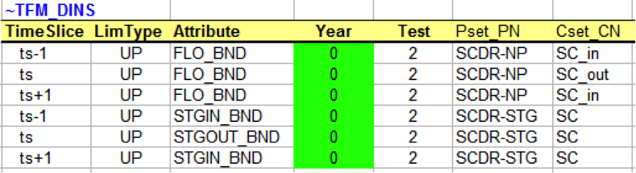
In order to bound the timeslice-specific flows to zero in all but the three flows {(ts,in),(ts– 1,out),(ts+1,out)} used in the constraint, FLO_BND, STGIN_BND and STGOUT_BND can be used, like shown below (only a few example timeslices shown here for illustration):
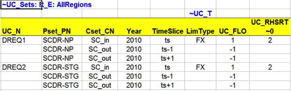
To define the constraint formulated, the following user constraints can be defined (assuming here that k1=k2=1 for simplicity):
I'm confused as to what "Test" refers to in these two tables above, as I've never seen it used before. Is it meant to represent something else? I can see that they are coefficients for a commodity balance in the upper table, but I'm not sure what the 2's represent in the lower table.
Also, my daynite timeslices are specified as T1 through T8, so for example I may shift from T6 (out) to T5 and T7 (in).
Is there a suggested place that I should place these ~TFM_DINS tables? Can they be placed in the same worksheet as the process characterization table?
Antti-L Wrote:
As one can see, the constraint specification is very straightforward, and looks exactly similar for both of the example SCDR technologies. Using any k1 / k2 would be equally easy.
I will attempt to modify the examples you've laid out for me in relation to the changes I described above and let you know if I have any additional questions.
Many thanks again for answering my questions. I really appreciate the help you've provided and hopefully I can get to the point where you advice actually translates to a working model on my end.
I am glad
if my reply and examples can be of some help.
If you
were confused about some of my points, so was I, about your original description.
Cyang Wrote:Our
service demands are have a timeslice profile (specified by COM_FR table) but
the end-use (demand) processes are specified as annual, such that only the
electricity input is daynite.
Well, that was obviously one source for
confusion. I agree that using annual level demands is reasonable, because that
makes the model smaller and the output distribution should usually not be
optimized. But from your original description I understood that the demand (SC) would be at
the DAYNITE level.
Cyang Wrote:Per
your suggestion, I am trying to implement the normal process.
Ok,
but I basically just suggested that if using the storage approach, you should
not define the user constraint.
Cyang Wrote:Can
you point me to the file/folder where I can view these equations for my own
model?
You can request the model equations to be listed in the listing
file. See the GAMS documentation for GAMS options.
Cyang Wrote:I'm
a little confused by the SCDR-NP process and why it uses both SC_in and SC as
inputs. My original intent was that the SCDR technology is downstream of the
demand processes (Cool1-3) so the outputs of Cool1-3 would be SC_in.
Well, you originally said that you want to create a DR processs for space
cooling demand (SC), and the input/output are SC_in and SC_out. I was confused that
the demand should be SC while the input/output are SC_in and SC_out. So, just
to make it exactly as you described, I decided to create dummy
commodities SC_in and SC_out and linked these to the demand SC. That is the
only reason why the SCDR processes in my example have both SC and SC_in as
inputs: to make my example follow your description.
Cyang Wrote:I'm
confused as to what "Test" refers to in these two tables above. [...]
I'm not sure what the 2's represent in the lower table.
Test is just a
name of a test region in my test model. You should see that the 2s are interpolation options for the zero bounds (because
Year=0). See the TIMES documentation about interpolation options.